NEW AGE DEVELOPING
Finding Ideas from Past Experiences
Coming out of project week, RPO writing and even after the exhibition, I somehow was still stuck at coming up with an idea for my next experiment. At times like this, I would try to think back of unique past experiences I have and see If i have any inspirations from there. I remember attending Isidro's film developing workshop, while I was recalling the process that I went through, I suddenly had an Idea: What If there was a way to develop images without going into a dark room and using chemicals? That idea instantly sparked my energy and curiousity and it was time to get to work!
To create a Touch-Visual-Audio interface that ignites people’s curiousity and interest in the craft of film photography and printing.
Users choose between 3 different film papers with text description of the image that it contains. They place it into the developer tray, containing “developer liquid”. Color sensor below detects the data in the film paper and triggers visuals and audio in TouchDesigner simulating a image slowly being developed. As the image develops, users can hear its corresponding soundscape slowly becoming more and more audible, till it fully develops.
After you take a picture, the film paper has an invisible picture on it which is called the latent image. To make that picture visible, you place the film into the developer bath. This chemical solution's job is to target the parts of the film that were hit by light and turn them dark. Specifically, the chemicals in the bath change the light-struck silver material into pure black silver, which creates the image. Controlling how long the film stays in the bath is very important, as this determines how dark and detailed the final picture will be. This experiment aims to provide a hands on experiment with the process of film developing, without the need to enter a dark room or to interact with chemical solutions.
Uncut Demo of Arduino Film Developer
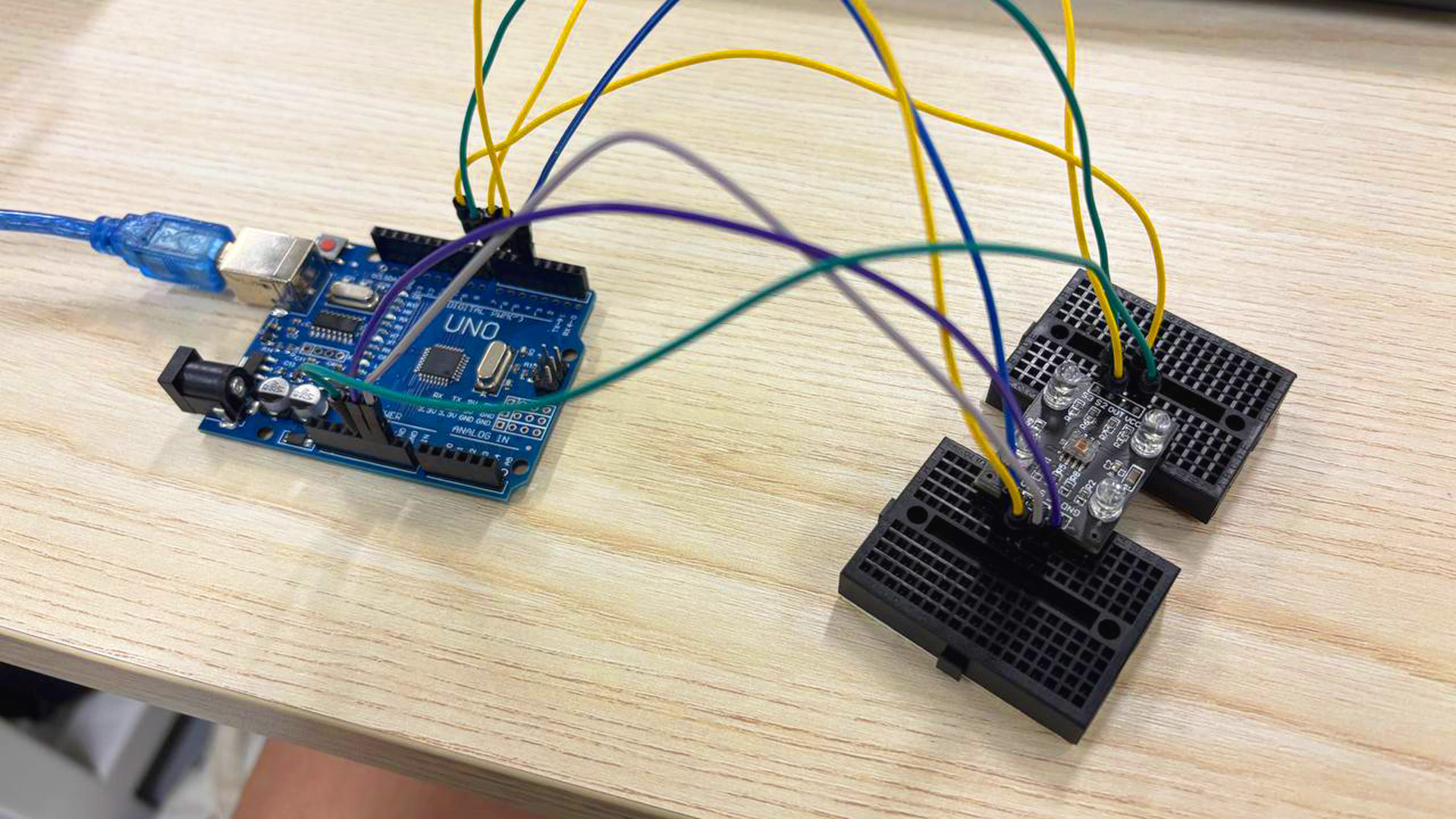
Attached the wires and set up the color sensor
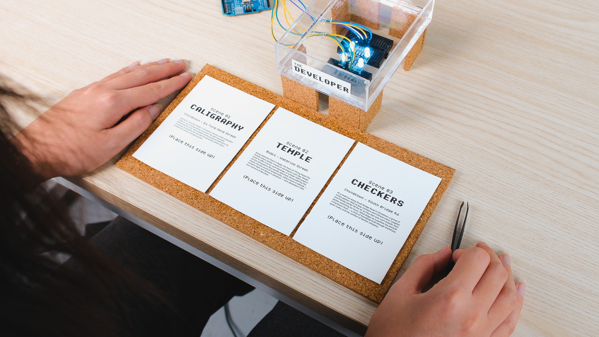
3 film papers with different description texts and "embeded" images
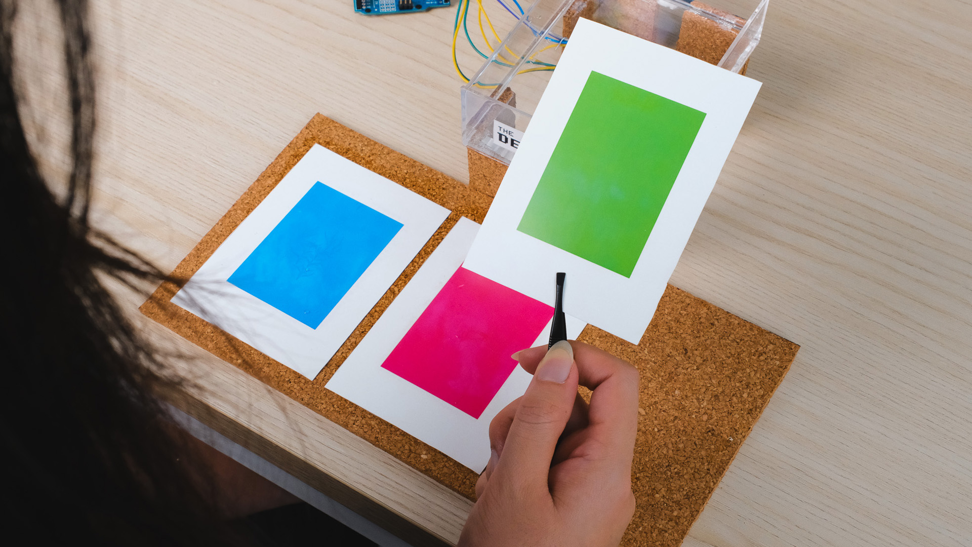
Printed 3 differet colors behind the film papers.
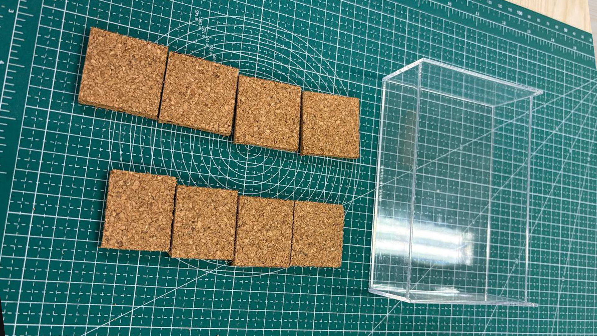
Cutting the components out and ready to be combined together
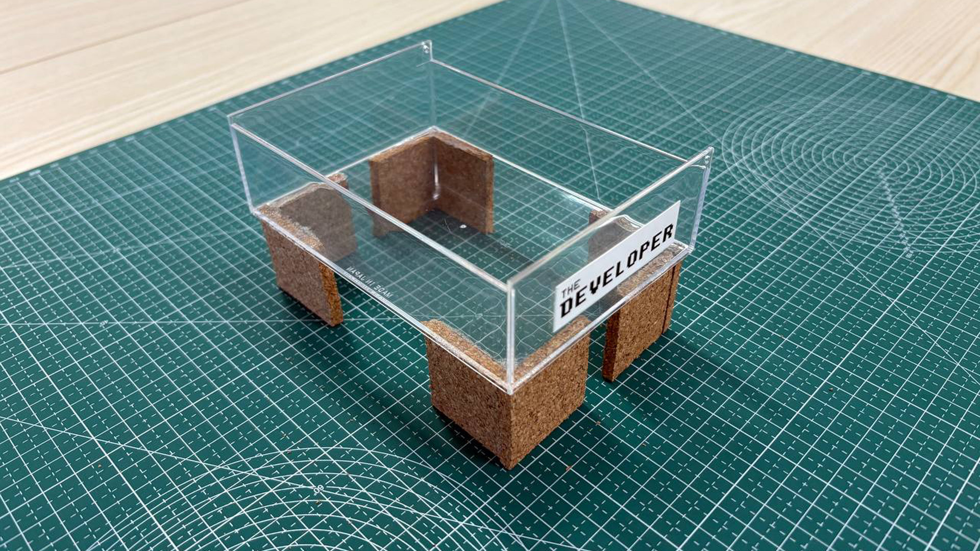
Final Developer Tray
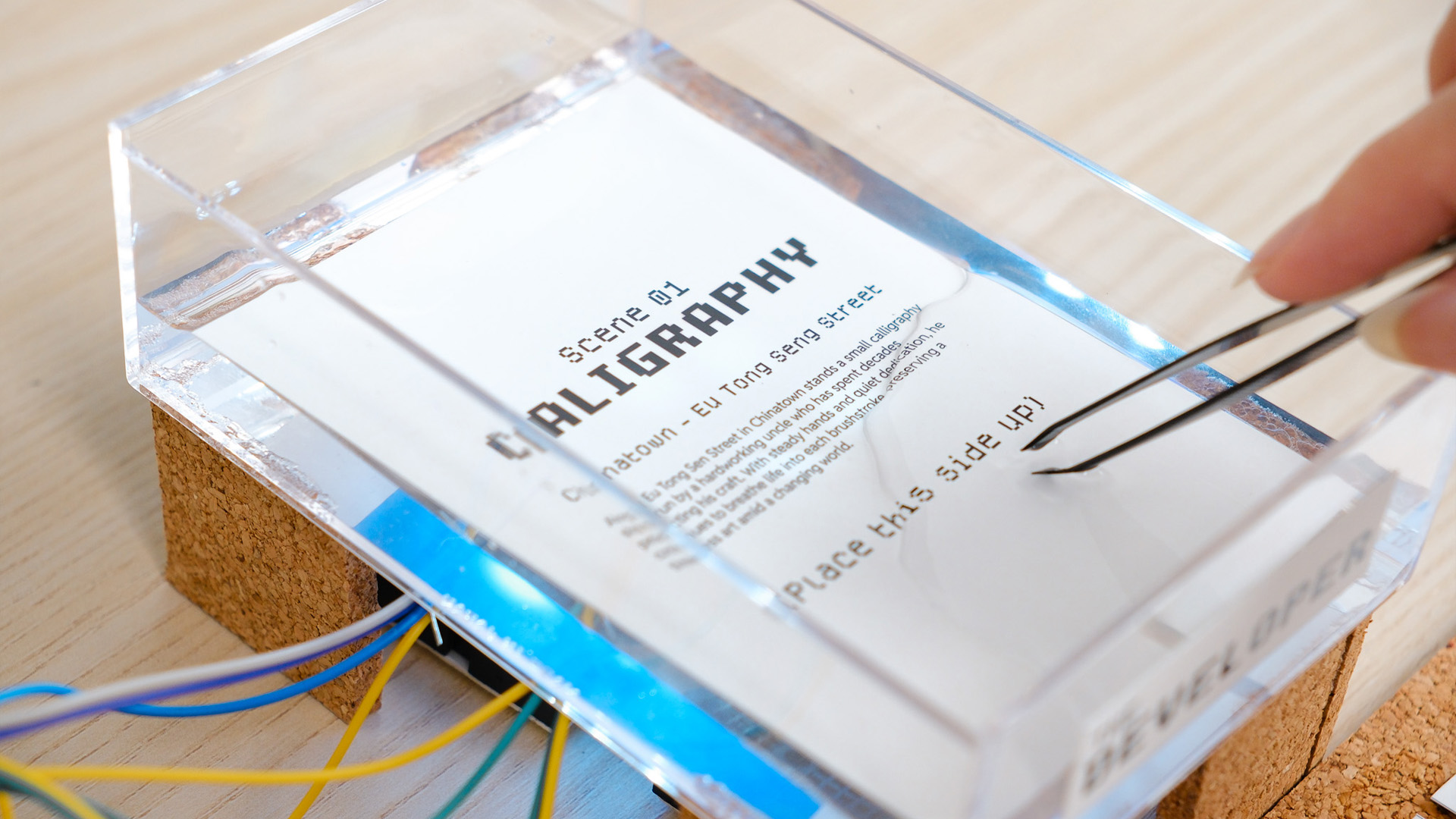
Dipping film paper into developer tray
I needed a way to swap out the visuals that is being developed just by simply changing the film paper. As NFC probably wont work in water, I decided to use color detection instead. I printed 3 different film papers with text descriptions of the image they contain and printed 3 different colors respectively on their flipped sides (Red, Green, Blue). I got the help of Claude to assist me in setting up the color sensor. I managed to generated a code that helps me send the color data from the color sensor into TouchDesigner. For the developer tray, I created one from a transparent tray with legs I attached to make it stand above the color sensor.
Great tutorial by PPPANIK
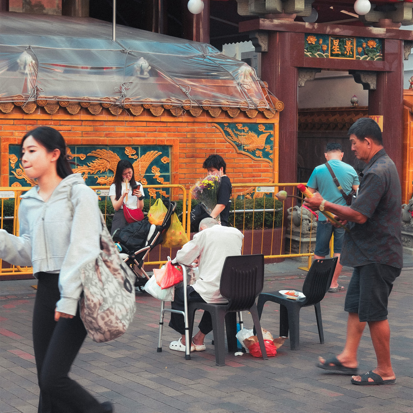
Original Image
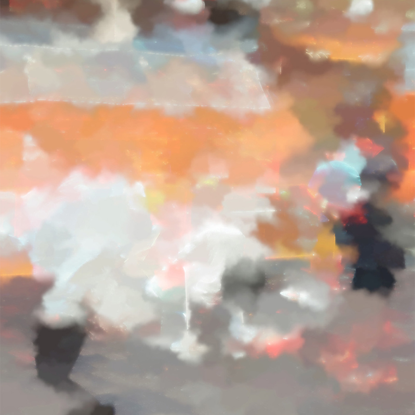
Watercolor Visual
I browsed youtube to learn some suitable visuals that I can add to my TouchDesigner Visual toolkit and also to be used for this experiment. I came across this tutorial by PPPANIK (a big TouchDesigner creator on youtube) that taught this cool water color visual. I watched the video and learnt how to build one myself. I felt that this type of visual fit well with the interaction and the concept of my experiment. Since the film paper is placed within the "Developer Liquid" (actually water), the water color visual made sense.
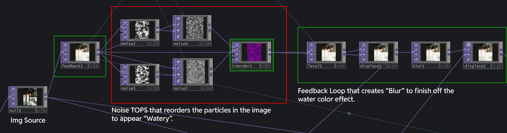
The Main Node Network that makes the visual work
To have a easier time understanding how I changed the visual, It will be helpful to understand how the visual works. Basically, after inputing the Image, I run it through a network of Noise TOPS that reorders the particles in the image to appear "watery". This Noise network is placed within a Feedback Loop, that creates "Blur" that finishes off the watercolor effect.
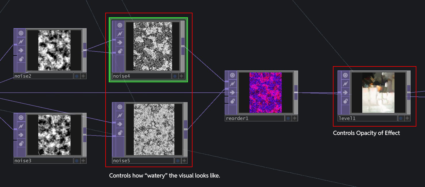
Noise4/5 controls the "watery" effect, Level1 control the opacity of the overall effect.
The visual I learnt was doing the reverse of what I wanted: It started off with a full image, then slowly dissipates away to the water color visual. I wanted the opposite to happen - water color forming to a clean image to create the feeling of "developing the image". I explored the Node network and discovered that the three key Nodes that affect the visuals most are Noise4, Noise5 and Level1. Above is the illustration of what they control.
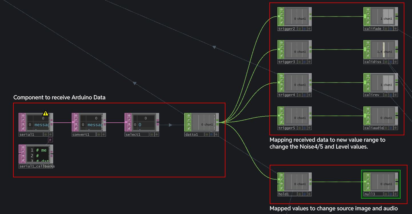
Arduino data imported with Serial DAT, mapped to various value ranges to change visual and audio
Knowing these key nodes, I managed to change the parameters for the visual to start from "water color visual" to clean image. I brought in Arduino's data with Serial DAT and mapped them to various ranges that affects the Level1 and Noise 4/5 TOPs to change the visual. I also linked the data to switch the audio that plays, so as to ensure that the right soundscape is played for its relevant image.
A big constraint that I noticed is that the whole set up is very sensitive to environment light. The light will affect the brightness of the colors at the back of the paper, and also the "0" value, resulting in jumpy visuals. For example, when the class light is on, I noticed that the GreenValue that the sensor reads for each of the images increases, crossing over the thresholds I set previously. This results in the wrong film papers triggering the wrong visuals.
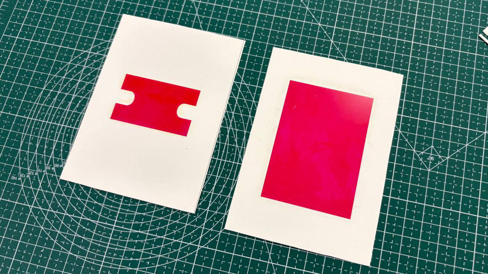
Increased the size of the colored rectangles
In my earlier iterations, the color printed behind the back was just a small rectangle because I thought it was enough. However, since the paper was smaller than the tray, it moved around, which affected the color reading. To fix this, I increased the size of the color rectangles to just be 3x bigger.
Andreas did like the outcome for my experiment (good to hear)! Seeing what I have done, he pointed out
a potential new direction for my graduation project, which is something I later adopted. It was the
direction towards experiential learning, where we use Multisensory Experiences and Interfaces to help
facilitate the learning of different concepts and topics through physical experiences. He gave
examples of where my style of work could fit into, such as science centres.
Honestly, It was a feedback I welcomed because in the end, it is still similar to my current topic,
except that i am no longer bounded by the constraints of visual arts and art museums.
In terms of the project outcome, I really enjoyed how it all worked out in terms of visual outcome and experience. The swap to color sensor worked really well, but probably not as reliable as NFC sensor due to the light constraints. However in a submerged setting, I cant complain! Following Andreas feedback, I actually feel more hopeful towards the direction of my project as it expanded my potential applications and context.
1. To explore ways to make the sensor work more reliably (set it under a fixed lighting?)
2. Towards sem 2, polish up on wiring neatness and making because its coming to prototyping season
(sem 2.)
3. To look into other possible applications and concept of experiential learning.